Via the menu item Import welding spots ..., weld points can be loaded from CSV files. In interaction with the task Move tool on path (extended) (see chapter Task library / Tool handling / Move tool on path (extended)), manual welding processes can be displayed and simulated.
CSV stands for “comma-separated-values” and thus represents a simple format for the exchange of structured data. A CSV file can be interpreted as table. The separators separate the columns within one line from each other. In principle, CSV files can be processed or created with any text editor. For more comfortable processing however, it is recommended to use special software tools additionally supporting processing (e. g. MS Excel).
The three imported / exported files have a similar structure. The following formatting rules must be observed:
iThe standard value separator is the semicolon “;”! iThe first line of each file serves as “head of table” and is NOT evaluated! iThe dot “.” is used as decimal separator for floating-point numbers! iThe apostrophe “‘ ” is no valid sign for import and export and should not be used in the data! |
The welding spots to be imported must be available as CSV file in the following format. Exactly one weld point group or one weld point is defined per line. The group assignment of the points is realised implicitly, i.e. each weld point is assigned to the last group defined (see figure figure Extract from a sample file for import).
# |
Column name |
Purpose |
|---|---|---|
0 |
Type |
A character string for distinction between groups and weld points: Gr for a new grouping Pt for a new weld point |
1 |
Name |
A character string for identification / designation of the corresponding weld points or groups. The character string is taken as object name during import. |
2 |
Matrix or position |
A 4x4 matrix as sequence of 16 values (separated by semicolon), describing the current transformation (position and orientation) of the object OR alternatively 3 values (separated by semicolon), only describing the position of the object. |

Figure 19: Extract from a sample file for import
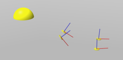
A weld group is a special marker (yellow hemisphere, see figure figure Weld group). It is a visual auxiliary object and can be masked out after the import. The weld group serves as group node for all subordinate weld points. Only by shifting this group node, it is possible to shift all weld points jointly. In contrast, weld points are normal markers and be shifted at will.

Figure 20: Weld group
iBy default, the weld group is created in the world coordinate system. |
The weld group is visible in Show as tree (see chapter User interface / Tab "Objects" / Tree view). Single weld points are displayed by expanding the substructure (see figure figure Weld group is shown as tree). In order to display an object’s substructure, one click on the object’s corresponding arrow symbol is sufficient.

Figure 21: Weld group is shown as tree