ema contains functionalities for the simulation and evaluation of HRC workstations. A tool for event-driven simulation adaptation has been developed in the simulation logic. For example, moving objects such as robots can be slowed down or even stopped by triggering the sensors.
Prerequisites for HRC scenarios are robots or objects that can be moved using IK, human models and sensors. Sensors could be the distance sensor objects described in section User interface / Tab "Objects" / Buttons /Insertion of objects / From library / Geometric primitives. In addition to this, any normal object could be converted into sensor object by defining the User defined object parameters - Latency [s] and speed adjustment (sensor event) [%] (see section Parameter types / User defined parameters / User defined object parameters). After simulating the scenario, the results are displayed in HRC report in results tab (see section User interface / Tab "Results"/ HRC report).
•Use of distance sensors as sensor objects
1 |
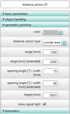
Configure the scan range of the sensor via the parameters |
2 |
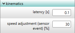
add optional sensor parameters to any objects via object context menu: •Latency [s] = reaction time of sensors •speed adjustment [%] = percentage speed adjustment when the sensor is triggered. |
3 |
Link between objects and sensors: •Using the user defined parameter sensor assignments, an object (for e.g. robot) could be linked to different sensors already defined in the scene. |
![]()
![]()
![]()
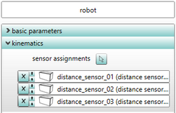
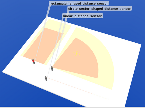
Figure 76: Use of distance sensors as sensor objects
•Definition of arbitrary geometries as sensor objects
1 |
import any geometric object into ema |
2 |
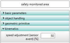
set the sensor event •Add the user defined parameter speed adjustment (sensor event) [%] (see section Parameter types / User defined parameters / User defined object parameters). •set a percentage value for this parameter and this value is used to adjust the speed of the robot when the sensor is triggered. |
3 |
link the robot to a (sensor) object •add the user defined parameter sensor assignments. •in order to set the new parameter select the (sensor) objects to which the robot need to be linked. |
![]()

![]()
![]()
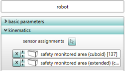
Figure 77: Definition of arbitrary geometries as sensor objects
•If sensors have been linked to objects (for e.g. robots) in the simulation, then the simulation calculation automatically switches to the event-based simulation mode:
oCalculation of worker behavior to generate worker movements
oDetection of sensor event (trigger) via collision check (human operator in the sensor range)
oRecording of the time of occurrence of sensor events
oCalculation of the robot path movement (geometric) based on the specified speeds
oAdjustment of robot speed based on the sensor events that have occurred (e.g. slowdown, stop)
oOutput of simulation results (motion data, process data, ...) for subsequent analyses
o3D visualization of the sensor areas and their states (for sensor objects)