The Line balancing is a method for optimizing the planning and distribution of several tasks at different stations. It is helpful for the individual process design of various operations and their temporal and spatial allocations in individual work stations. Here, aim is to identify the optimization potentials with minimum effort by aligning workplaces and tasks along with the workers within the production cycle. If the Line balancing is activated, then by linking the work place to workstation, the allocation to a production cycle will get displaced with the relative position of the workstation.
The pre-requisite for using the line balancing feature is a well-defined structure of geometric objects (corresponding to each objects in the scene), with structural properties and process locations defined in the scene graph. Process location is any node in the object tree under which all the relevant objects of the operation can be found as subnodes.
For example, these includes:
▪Tools
▪Furniture
▪Products/components
▪Related to the helper objects (grasp points, ...)
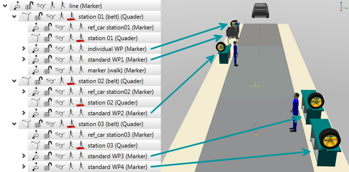
The figure below, show different process locations (Standard AP1 to Standard AP4 and Individual AP) defined. (see figure A sample partial scene graph).

Figure 73: A sample partial scene graph along with the corresponding 3D view and the allocation of objects/process locations for line balancing
After configuring the layout of the process location it can be linked to any behavior group that includes relevant processes of this process location. The methodology to use Line balancing is described as in the following steps:
1)Behavior group with linked process location
a)Context menu of a behavior (a task group)
b)Parameter --> edit user defined parameter
c)Append process location to the behavior (see chapter Parameter types / User defined parameters / User defined task parameters)
d)Link the process location to an object in the scene
2)![]() /
/![]() Pressing the button Enable/disable line balancing functionality
Pressing the button Enable/disable line balancing functionality
a)The button is highlighted with the background color
b)The behavior linked to this process location in any case will also be similarly highlighted (see figure Comparison between enable and disable line balancing).


Figure 74: Comparison between enable and disable line balancing
3)Implementation of line balancing
a)Moving the linked behavior groups using Drag and Drop to another human model causes:
Case 1 - Target human model already contains behavior groups linked to the process location --> Parent node of the first found process location in behavior is used as insert location for the process location of moved behavior group
Case 2 - Target human model does not contain behavior group with linked process location
Case 2a - the target human model itself is linked to a process location (user defined parameters Process location of the category Line balancing and variants (see chapter Parameter types / User defined parameters / User defined task parameters) --> Parent node of the process location of target human model is used as the insert location for the process location of moved behavior group
Case 2b - the target human model is not linked to process location --> scene graph root is used as the insert location for the process location of moved behavior group (Warning: Relative transformations of the moved resource locations will be lost.