In order to create a path map, the interaction mode (see section User interface / 3D settings / Interaction modes) must be switch to path map.
When the path map editor is active, the middle and right mouse buttons are used for navigation as usual. All actions with the path map editor are carried out using the left mouse button.
iA path map can be created only on a floor object. |
The path map consists of nodes and segments. When the left mouse button is first clicked on the floor object, a new node is created (green, see figure Nodes and segment). The automatically created yellow node is movable and can be used to create a path segment. The last created node is always the new active node for the creation of the following path segments.
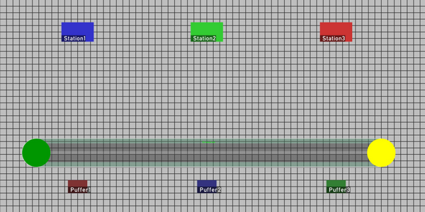
Figure 145: Nodes and segment
Nodes can be moved by selecting the node with a left click and without releasing the click moving the mouse (blue, see figure Move node). When aligning with other nodes a green help line appears. The manipulated node is briefly pinned to other orientation nodes.
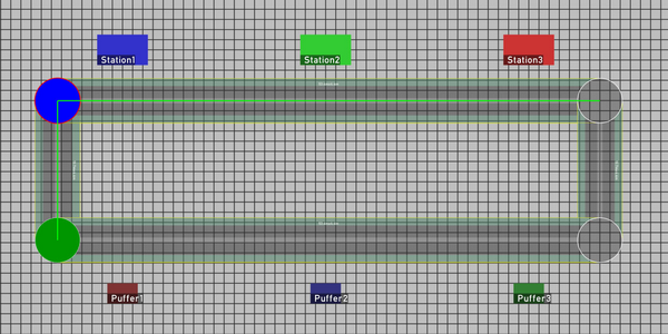
Figure 146: Move node
It is possible to insert new nodes on existing segments or to activate existing nodes (green, see figure Add node on segment Insert node on segment).
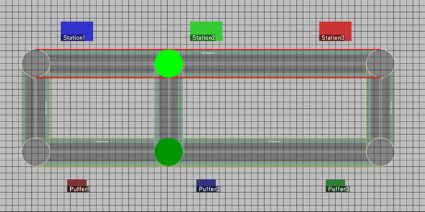
Figure 147: Add node on segment
With a double left click on the centre of the node or segment, the node or segment is deleted. If the mouse is moved between the two clicks, no deletion takes place.
A left click on the displayed dimension of the segment switches the segment type. According to the workplace directive, there are 7 segment types with driveways (on both ways or on one way), footpaths and
shoulders (see figure Segment types).
Segments from left to right in figure Segment types are the following:
1. footpath (width: 0.8m)
2. and 3.: one way path with shoulder on both sides (width: 2.2m)
4. and 5.: one way pathl with footpath on both sides (width: 2.7m)
6th: two way path with shoulders on both sides (width: 3.9m)
7th: two way path with foot path on both sides (width: 4.4m)
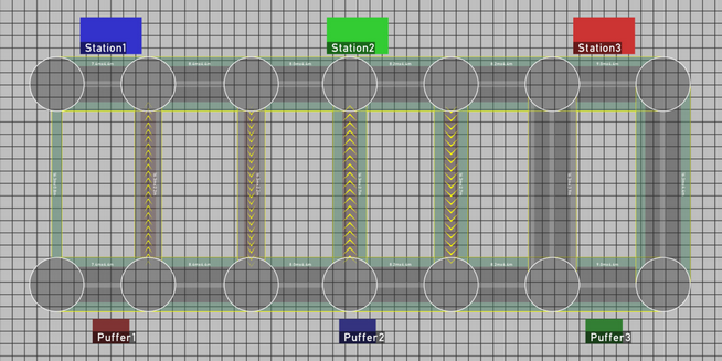
Figure 148: Segment types
Without a path map, the material flows of the imported ema Plant Designer data are displayed directly (see chapter Data Export and Import / ema Plant Designer). When using the path map the material flows across the paths. The routes are displayed when the mouse pointer is placed over the direct arrow between source and sink, the source or the sink (see figure Routing of material flows). After switching to layout mode, when the mouse pointer is held over the stations or buffer locations, additional information about the route length is displayed. When the layout is changed the route lengths or the routing are updated in real time (route network, source or sink).
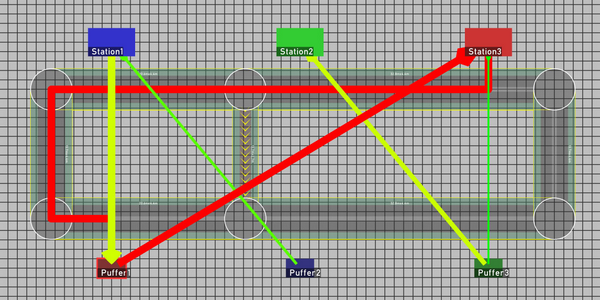
Figure 149: Routing of material flows
Material flows that cannot be routed are marked with a no-entry sign (see figure Material flow with no possible path). The reason for this is could be either a missing segment or segment which is a one way segment.
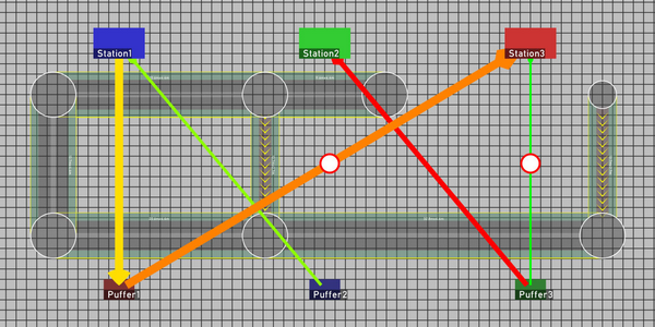
Figure 150: Material flow with no possible path
The utilization of the individual segments of the path map is indicated by a color (green to red). This so called heat map display updates automatically when the layout positions or the paths themselves are changed (see figure Heat map).
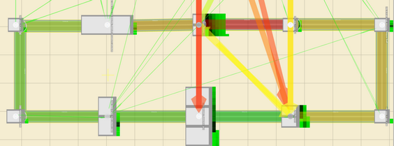
Figure 151: Heat map
Via the submenu ema Plant Designer in the menu bar path maps can be imported and exported (as *.emaPathmap files) as well as deleted. More information to the Plant Designer can be found in the chapter Data export and import / ema Plant Designer.