The context menu of an object can be opened by a right click on the list/tree view of the object or a right double click on the object in the 3D view. The context menu contains certain commands depending upon the type of the object.
Group |
Icon |
Function |
Object types |
Description |
|---|---|---|---|---|
Manikin |
|
Configure manikin |
Limited to manikin |
Dialog box for selecting a manikin which can replace the existing manikin. |
Manikin |
|
Set body posture |
Limited to manikin |
Options for initial posture adjustment (standing, upright (initial posture) - standing, upright (keep arm posture) - sitting, upright - sitting with trunk extension) |
Manikin |
|
Create / remove reach space (DIN EN ISO 14738) |
Limited to manikin |
Creates a reach space object (see chapter User interface / Tab "Objects" / Buttons / Insertion of objects / From library / Geometric primitives). The default values are based on the selected human model (male/female) and the height percentile according to DIN EN ISO 14738. The generated reach space object is hierarchically attached below the selected human model and is located at the height of the elbow joint. The reach space is based on the formulas of the calculation method according to DIN EN ISO 14738:2005 under use of population specific anthropometric data (see sources on anthropometry). |
Manikin |
|
Create / remove 3D reach space (Hettinger & Wobbe, 1993) |
Limited to manikin |
Creates a 3D reachspace according to Hettinger & Wobbe (1993). The reachspaces depend on the respective human model and its individual dimensions.
The three reachspaces according to Schmauder & Spanner-Ulmer (2022) are as follows: •red = anatomically maximum reachspace (upper arm length) •yellow = physiologically large reachspace (reduction of the anatomically maximum reachspace by 10 %) •green = physiologically small reachspace (forearm length)
The reachspaces always refer to the immobile upper body. No distinction is made between sitting and standing.
The 3D reach space object can be displayed for the left, right, or both sides. Its transparency can be changed. |
Creation |
|
Set object as alternative insertion root |
All objects except human model and body part |
If the selected object is defined as alternative insertion root object (see chapter User interface / Tab "Objects" / Buttons) it is used as the parent for newly added objects. The object is placed using the local position and orientation options in the Add object from library dialog. An extra option available is the checkbox Activate usage of alternative insertion root object. It is enabled by default (see chapter User interface / Tab "Objects" / Buttons). The advantage of this feature is that objects created in georeferenced scenarios, potentially far from the origin itself, can be placed at the desired position quickly. |
Creation |
|
Create new group with master object |
All objects |
Creates a new object group with the selected object as the group master. Group members can also be added to this group. Further possibilities to edit the object group can be found in chapter User interface / Tab "Objects" / Buttons. |
Creation |
|
Create new group with member object(s) |
All objects |
Creates a new object group with the selected object(s) as the group members(s). Group master can also be added to this group. Further possibilities to edit the object group can be found in chapter User interface / Tab "Objects" / Buttons. |
Creation |
|
Add as group member |
All objects |
Adds the selected objects to an existing object group as group members. The object group to which these objects need to be added is selected via a dialog window. Further possibilities to edit the object group can be found in chapter User interface / Tab "Objects" / Buttons. |
Creation |
|
Remove from all groups |
All objects |
Selected objects will be removed from all available object groups. |
Creation |
|
Create assembly template |
All objects |
A new assembly template will be created from the selected object as a locked reference with structure. This is used to store the end position of components in the assembly; target objects are found automatically in the structure. As a documentation parameter the checkbox is assembly template is activated. The created objects have the prefix "AssemblyTemplate_". If the object has been changed since it was loaded, a dialog appears in which the assembly template can be created based on the initial structure. |
Creation |
|
Copy object |
All objects |
Copies the object and inserts it at the same position. |
Creation |
|
Copy object (with structure) |
All objects except body part |
In addition to function Copy object this function copies not only the selected object but also all of its hierarchical child objects. Afterward, the copied object structure will be situated at the same geometrical location like the original. With this functionality whole workplace layouts or racks completely occupied with objects can be duplicated easily. Only restriction is that all sub objects have to be hierarchical children of the top level object (see chapter Menu bar / Options / Settings / User interface). |
Creation |
|
Add marker with object matrix |
All objects |
Creates a marker using the object matrix of the selected object. |
|
Create reference for object |
All objects |
Creates a Reference object from the given object. The reference object is a simple copy of the original object without any structural hierarchy and is realized by reference to the original object's sub-tree. The reference object could be used as target object in task parameters. In contrast to physical object copies, the underlying files and object structures do not need to be reloaded. Thus, the use of reference objects instead of object copies is preferable due to performance reasons. References have the parameter full original structure, that differentiates between the visualization of the full original object structure geometry (checked) or only displaying the single original object geometry (unchecked). |
|
Creation |
|
Add label to object |
All objects |
Adds a label to the selected object which is inserted in the object tree under the corresponding object. |
Creation |
|
Save active object in file |
All objects except human model and body part |
The selected object can be exported in different formats. |
Transformation |
|
Set root as parent |
All objects except human model and body part |
Attaches the selected object under the scene graph root. |
Transformation |
|
Set parent |
All objects except human model and body part |
Attaches the selected object in the scene graph under another object to be selected. |
Transformation |
|
Merge object structure |
All objects except human model and body part |
Merges the selected object with its substructure to a single object. |
Transformation |
|
Adopt matrix of other object (global) |
All objects except human model and body part |
An object selection dialog is opened and after successfully selecting an object its global transformation data will be applied. |
Transformation |
|
Repair scaling |
All objects |
The repair scaling dialog opens. A description of the repair options can be found in chapter Menu bar / Edit. |
Transformation |
|
Select endeffector |
All objects except body part |
Selects the endeffector object of a kinematic chain. In the case of multiple endeffectors, an object selection dialog appears, with which the desired endeffector can be selected. |
Coordinate Origin |
|
Reset object origin |
All objects |
Resets the coordinate origin of the selected object. |
Coordinate Origin |
|
Apply origin from another object |
All objects |
An object selection dialog opens to select a source object to adapt the coordinate origin from. If successful, the object symbol will be overlaid with a colored coordinate origin, e.g. for a cuboid: |
Coordinate Origin |
|
Set origin in bounding box center (move origin) |
All objects |
Moves the coordinate origin to the center of the bounding box of the selected object. |
Coordinate Origin |
|
Set origin in bounding box center (move geometry) |
All objects |
Moves the geometry so that the coordinate origin is in the center of the selected object's bounding box. |
Edit |
|
Copy to clipboard (object structure only) |
All objects except body parts |
The selected object with its substructure will be copied to the clipboard. |
Edit |
|
Copy to clipboard (object structure & assigned behaviors) |
All objects except body parts |
The selected object with its substructure will be copied to the clipboard. In case of human models or dynamic objects the associated behaviors are also copied to clipboard. |
Edit |
|
Insert from clipboard |
All objects except body parts |
The copied object structure in the clipboard will be hierarchically inserted below the selected object. By choosing paste original objects the object will be inserted like it was copied. With paste replacement objects the individual objects are replaced by geometric primitives (cuboid) based on their bounding boxes. In case of human model or dynamic object with connected tasks are copied to the clipboard, then the behavior will also get inserted. |
Edit |
|
Delete selected object(s) |
All objects except body parts |
The selected objects will be deleted. |
Behavior |
|
Add behavior |
All objects except human model |
Adds a behavior (object movements) to the object. In doing so, a task bar is added in the tab Tasks. The tasks are dragged into the task bar (see chapter User interface / Tab "Tasks"). Object node gets a different color, which indicates that now tasks could be assigned to this object. |
Behavior |
|
Remove behavior |
All objects except human model |
The task bar is removed again. |
Visibility |
|
Display all objects of the same type |
All objects |
Displays all objects of the same type. |
Visibility |
|
Mask out all objects of the same type |
All objects |
Masks out all objects of the same type. |
Visibility |
|
Zoom on (sub)objects |
All objects |
Zooms to all subobjects of the respective node / object based on their bounding boxes. This functionality is especially helpful for objects where the coordinate origin is displaced from the geometric center. |
Parameter |
|
Edit user defined parameters |
All objects except human model and body parts |
Pressing the menu item opens a dialog Manage userdefined parameters of ... (see chapter Parameter types / User defined parameters). |
Parameter |
|
Transfer parameters |
All objects except body parts |
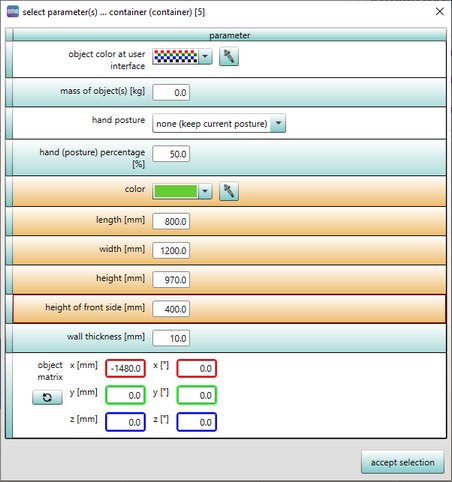
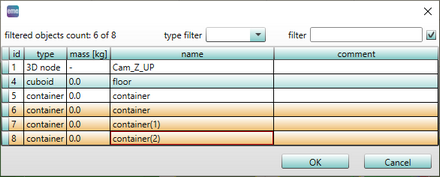
This menu item can transfer parameters defined for an object to other objects. A dialog box will open (see figure required parameters) wherein the required parameters of the object that need to be transferred can be selected (using the checkbox). After this a dialog box (see figure Selection of required objects) will be opened wherein the object(s) on which the selected parameters need to be applied can be selected and press OK in the dialog box to complete the parameter transfer. |
Parameter |
|
Replace object in task parameters |
All objects |
Replaces the object in all tasks in which it is used by another object. |
Parameter |
|
Apply comment color on object |
Human model and geometric primitives |
Transfers the comment color of the level corresponding to the object in the Tree view to the object in the 3D view. |
Parameter |
|
Fetch comment color from object |
Human model and geometric primitives |
Synchronizes the comment color of the level corresponding to the object in the Tree view with the color of the object in the 3D view. |
Movement / risk space |
|
Create movement area |
All objects |
This function creates a voxel grid that represents the space the object occupies during the simulation. |
Movement / risk space |
|
Create risk area (speed dependent) |
All objects |
Extension of the movement area by a speed-dependent safety distance (based on ISO/TS 15066 ). |
Movement / risk space |
|
Create reach space object |
All objects |
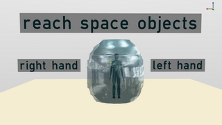
For a user selected node in the kinematic chain (see chapter Task library / Tasks (basic objects) / Complex object FK (Forward kinematics) and Task library / Tasks (basic objects) / Complex object IK (Inverse Kinematics)), a closed 3D object could be generated, whose interior space represents the complete set of points, the user selected node in the kinematic chain can reach by manipulating the available DOFs (External reach space). For e.g. by selecting the end effector (TCP/Hand joints in case of robots/human model), the complete 3D space where the robot/human model can reach could be generated. In addition to that, the 3D region where the selected node cannot reach (Internal reach space) can be computed and visualized as a closed 3D object (see figure Reach space objects). The generated 3D objects are stored as collada files in emaGeometry folder (see chapter User interface / Menu bar / File). |
|
|
Hide |
All objects |
Object will be become invisible in the 3D view and the corresponding flag is set in the object tree and list view (see chapter User interface / Tab "Objects" / List view). |
|
|
Show |
All objects |
Object will be become visible in the 3D view and the corresponding flag is set in the object tree and list view (see chapter User interface / Tab "Objects" / List view). |
|
|
Set collision object flag |
All objects |
Collision object flag is set for all selected objects (see chapter User interface / Tab "Objects" / List view). |
|
|
Remove collision object flag |
All objects |
The set collision object flag is removed for all selected objects (see chapter User interface / Tab "Objects" / List view). |
|
|
Set floor object flag |
All objects |
Floor object flag is set for all selected objects (see chapter User interface / Tab "Objects" / List view). |
|
|
Remove floor object flag |
All objects |
The set floor object flag is removed for all selected objects (see chapter User interface / Tab "Objects" / List view). |
|
|
Lock structure |
All objects |
Locks the hierarchical structure of an object. The child nodes of the object could not be edited any more and are greyed out in the tree view. These child nodes could not be individually selected in the 3D view. |
|
|
Unlock structure |
All objects |
The locked structure will be released for editing. The child nodes are no longer greyed out in the tree view and could be individually selected in the 3D view. |
|
|
Structure lock all objects on same level |
All objects |
Locks the hierarchical structure of an object as well as of all further objects that are located on the same level beneath a parent object. The child nodes of these objects can not be edited any more and are greyed out in the tree view. These child nodes can not be individually selected in the 3D view. |
|
|
Expand all (sub)nodes |
All objects |
Expands the complete tree structure below the selected nodes. |
|
|
Expand next level (sub)nodes |
All objects |
Expands the tree structure below the selected nodes by one level. |
|
|
Contract all (sub)nodes |
All objects |
Contracts the complete tree structure below the selected nodes. |
Assembly templates, object copies, markers with object matrix and references created via the Create menu are each inserted on the same level as the original object.

Figure 50: Reach space objects
![]()
Figure 51: Display of the symbols within the object entry in the tree view

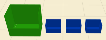
Figure 52: Before transferring the parameters

Figure 53: Required parameters

Figure 54: Selection of required objects

Figure 55: After transferring the parameters