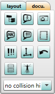
Tips and comments pertaining to the objects and tasks can be seen in the 3D view. These information can be defined in several places and then can be turned on/off using the buttons available in the Documentation area in the 3D view (see figure Documentation buttons on).

Figure 158: Documentation buttons on
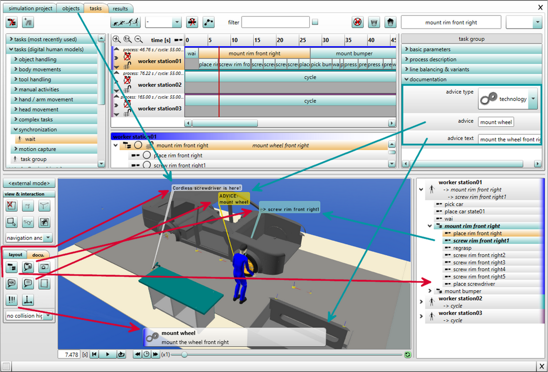
The information is provided in different forms; a textual description of the information is provided in the table (see table Location and the representation of the documentation information) and a pictorial description is provided in the figure (see figure Representation of the documentation information). The red arrows in the figure connects the information displayed in the 3D view and the corresponding button. The turquoise colored arrow connects the information in the 3D view to the corresponding source where this information is defined.
Buttom |
Icon |
Function / Defined in |
Represented as |
|---|---|---|---|
Switch 3D comment mode |
|
Show / Hide 3D commend mode User defined comment field (see chapter Parameter types / User defined parameters / User defined object parameters). |
White text label from the center of the bounding box |
Switch 3D instruction mode |
|
Show / Hide 3D instructions Short description of the advice (see chapter Parameter types / User defined parameters / User defined task parameters). |
Yellow text label from the center of the bounding box |
Switch 3D task name mode |
|
Show 3D task names (all) Show 3D task names (humans only) Hide 3D task names Naming of the tasks in the tab Tasks |
Light blue text label from the center of the bounding box |
Switch task overview visibility |
|
Show / Hide the task overview list on the right side of the 3D view. |
Task overview on the right side of the 3D view |
Switch 2D instruction mode |
|
Show / Hide 2D instruction mode User defined comment field (see chapter Parameter types / User defined parameters / User defined task parameters). |
Label towards the lower side of the 3D view |
Switch object measurement labels mode |
|
Switch object measurement labels mode This only applies to objects to which the User defined parameter - show measurement label is set (see section Parameter types / User defined parameters / User defined object parameters). The text size can be adjusted using text size of measurement labels [mm] in 3D Viewer in options. (see section User interface / Menu bar/ Options/ Settings/ 3D viewer). |
Label on the object Bounding Box |
Switch object information |
|
Show / Hide object information (e. g. utilization indicators) This only applies to data transferred from the emaPD (see Data Export and Import / ema Plant Designer). |
Utilization indicators above stations |
(De)activate ergo color coding for human models |
|
Color codes body parts according to the limit values for body angles set in the Chart options. When clicking the button, the different angles for the head, upper body and arms are selectable. It is based on the charts of the Spine, Arm and Head values. |
Yellow / orange / red coloring of the head / upper body / arms of the human model |
Save screenshot (F12) |
|
By pressing the button Save screenshot (F12), an image of the current scene is saved in jpeg format. The directory where the screenshots need to be stored can be specified in advance in storage locations menu in ema settings (see chapter User interface / Menu bar / Options / Settings / Storage locations). If the storage location is not previously defined, then the screenshot is saved directly in the project folder itself. |
- |
Save video file |
|
Using the button Save MP4 video file, the simulation is saved as video in .mp4 format. For that purpose, the memory location and the file name must be indicated. A successful simulation run is the precondition for using this feature (see chapter User interface / tab "Tasks" / Buttons). It is possible to select popular resolutions (UHD 4K, FullHD, HD, Mini and Current window resolution) for exporting the videos. The video is created at the currently set playback speed. |
- |
Enable / disable flow visualization in 3D view |
|
Shows or hides the walking routes of a human model as path lines. The arrows indicate the direction of movement. The arrows can be (de)activated by default after a new simulation using the option Show walking paths in the 3D window after each simulation (see chapter User interface / Menu bar / Options / Settings / 3D view). Further information on the paths can be found in the spaghetti diagram results section (see chapter User interface / Tab "results" / Spaghetti chart). |
Path lines in color of the human model |
Figure 159: Location and the representation of the documentation information

Figure 160: Representation of the documentation information